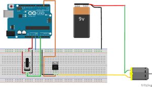
Arduino/DC Motors/PWM with transistor
Basics
First Sketch

We use a variable resistor to change the duty cycle.
The motor is powered by any DC source.
The middle pin on the transistor is the control pin.
The left(flat/labeled/non-Heatsink) side is the ground.
The right pin is the voltage return to ground.
You power the motor from the positive side of the battery.
The potentiometer simply
#define pwm 3 // Use pin 3 for the pwm output.
#define pot A0 // the resistor will go on analog input pin 0
void setup() // put your setup code here, to run once:
{
pinMode(pwm,OUTPUT); // Define pin pwm as an output.
pinMode(pot,INPUT); // Define pin pot as an input.
Serial.begin(9600); // Start the serial monitor.
analogWrite(pwm,0); // Make sure the motor is off.
}
void loop() // This is the main code that runs till power off.
{
float val = analogRead(pot);
float duty = map(val,0,1023,0,255) // Change the input range of 1023 to the output range of 255
analogWrite(pwm,duty); // Set pin pwm to duty value.
Serial.print("PWM = ");
Serial.print(pwm); // Print the pwm value.
Serial.print(" ");
Serial.println(duty); // Print the Duty value and then do a carriage return.
}